Visual System
Projection Screen
The 3 projection screens are mounted on 3 customized
metal frames. The metal frames are fitted with
wheels. This makes it easy to move the screens away
for maintenance purposes, without the danger of
bruising the floor. Each metal frame holds a 163cm x
123cm (5,35ft x 4.04ft) MDF panel, painted with a
special screen-paint.
Projector / Screen System
For the verification of
the proper alignment
of the projector
/ screen system
a grid test pattern is recommended. Some
projectors, like the BQ MX613ST, have an option to
generate pattern internally. If not, you can draw a
simple grid test pattern by yourself with your
favorite graphics program or search for
it in the Internet.
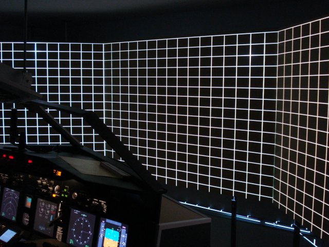
Perfect aligned projector
/ screen system. Essential for a successful image
alignment
Creating the Cockpit Views
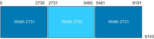
As the FS9, FSX and P3D are also using a universal screen co-ordinate system, which makes the co-ordinates independent of the of screen resolution. A maximum spanned view is represented by 8192 width and 6144 height. The recommended positions for the 3-window setup are as follows*:
- Forward Left window:
ScreenUniCoords= 0, 0, 2731, 6144 - Center window:
ScreenUniCoords= 2731, 0, 2730, 6144 -
Forward Right window:
ScreenUniCoords= 5461, 0, 2731, 6144
* As it applies to my the 135 degree projector /screen system with 3 BQ MX613ST 4:3 projectors. For more information, click here: Visual Setup
Camera Definitions
With FSX the so called 'camera system'
has been introduced. The camera system defines what appears in each view window. Each camera definition has its own Global Unique ID (GUID). The default GUID for the Cockpit View is {B1386D92-4782-4682-A137-738E25D1BAB5}. All settings releated to the cockpit view are referenced by that GUID.
The system differentiates Global Cameras, Aircraft Cameras, and Flight/Mission Cameras.
The camera definitions are part of the flight (.FLT) file, which is used when a session is saved off. On Vista / Win7 the location of the FSX *.flt files is: C:\<Your Username>\Documents\Flight Simulator X Files\ . For P3D use: C:\<Your Username>\Documents\Prepar3D Files\
For more information regarding camera configuration check either FSX SDK
http://msdn.microsoft.com/en-us/library/cc526984.aspx
or for P3D SDK: http://www.prepar3d.com/support/sdk/
I explain that here because in the next step it is necessary to know about it.
Customized Flight File
For a start, I recommend the following procedure (3 projector setup with a 135 degrees FOV, 4:3 projectors):
-
1. Save a current scenario as new flight, name it e.g. 'visualsetup3P'
-
2. Download the *.flt snipped from the link below and paste it into the saved flight *.flt file, by replacing the original windows and camera definition in that file.
3. Reload the saved flight
Download link flt snipped: FLT_Snipped.txt (new version, zoom corrected)
--> The new zoom value was calculated with the tool 'Windowmaker', provided by Wayne.
Read also this thread: http://www.mycockpit.org/forums/showthread.php/23199-Windowmaker-tool-updated!
For my setup I have set Wideviewaspect=FALSE (check FSX.cfg / Prepar3D.cfg).
If everything went well, you should now have a nice 135 degrees FOV projection, which consists of a spanned background view and 3 windows for left, center, and right view. The backdraw is that your system has to handle in sum 4 windows. Depending on your systems overall performance this solution might not satisfy your frame rate expectations. However, I was using this solution for quite a while, until I found a different approach, discussed at Cockpitbuilders.com and Prosim737.com.
Alternative approach without spanned view
With the settings based on the discussion in the above metioned forums I could gain a approx. 25% higher frame rate. This approach does not use a spanned fourth window in the background. Instead a transparent panel view is used. All what you need is an adapted .flt file and a transparent panel BMP. You can find all needed information in the above mentioned treads. For the zoom and rotation calculation I recommend the 'Windowmaker' tool. It is easy to copy / paste the results from 'Windowmaker' to the 'Three Window' flight file (.flt).